In the precise world of medical imaging and industrial testing, ultrasound coaxial cables serve as the critical link that ensures… - Professional Ultrasound Coaxial Cable Solutions
Learn more about, latest news, frequently asked questions
In the precise world of medical imaging and industrial testing, ultrasound coaxial cables serve as the critical link that ensures high-frequency signals travel accurately between transducers and imaging systems. These specialized cables are engineered to maintain signal integrityunder demanding conditions, but like any component, they can develop faults that compromise performance. Continuity testing provides the first line of defense against signal degradation, helping technicians identify breaks or shorts before they impact diagnostic accuracy or measurement precision .
Unlike standard coaxial cables, ultrasound variants are designed for specialized applications requiring exceptional electrical characteristics and physical durability. These cables typically consist of a silver-plated copper conductor, fluoropolymer insulation (PFA/PTFE), multiple shielding layers, and medical-grade jacketing materials . What sets them apart is their precise impedance control(typically 50Ω ± 2Ω) and low signal loss (<0.15 dB/m at 1 GHz), which are essential for maintaining the fidelity of high-frequency ultrasound signals .
The global market for ultrasound coaxial cables is projected to reach approximately $850 million by 2033, driven largely by medical imaging applications which account for over 60% of production . These cables must withstand unique challenges including repeated flexing, sterilization cycles, and proximity to other electronic equipment while maintaining signal integrity—a requirement that makes regular continuity testing essential for preventive maintenance .
Proper continuity testing requires specific tools that match the precision requirements of ultrasound applications:
FRS ultrasound coaxial cables are engineered with testing compatibilityin mind, featuring standardized impedance values and durable connectors that ensure reliable contact during testing procedures. This design foresight simplifies maintenance protocols in clinical and industrial settings where downtime costs are significant .
Before testing, ensure all devices are powered off to prevent electrical shock or equipment damage. Visually inspect the cable for obvious damage such as cuts, kinks, or connector deformation . For medical applications, follow appropriate sterilization protocols if testing cables that may contact patients .
For FRS ultrasound coaxial cables, the expected resistance reading for a 1-meter cable typically falls between 0.05-0.15 ohmsfor both center conductor and shield when properly terminated. Values outside this range suggest potential issues requiring further investigation .
While basic continuity testing identifies complete breaks or obvious shorts, advanced methods provide deeper insights into cable health:
TDR testing sends a pulse down the cable and measures reflected signals to pinpoint the exact location of faults or impedance variations. This method is particularly valuable for identifying partial breaks or subtle damage that doesn’t completely disrupt continuity but still degrades signal quality .
This advanced technique measures the amount of signal reflected back toward the source due to impedance mismatches. For ultrasound applications where image clarity depends on precise signal transmission, return loss testing can identify developing issues before they impact diagnostic confidence .
FRS cables undergo 100% electrical testingduring manufacturing, including TDR analysis that verifies both continuity and impedance stability throughout the entire cable length. This commitment to quality control ensures consistent performance in critical applications .
Continuity testing protocols vary across industries that utilize ultrasound coaxial cables:
In medical applications, cables must comply with ISO 13485for quality management and IEC 60601for electrical safety. Regular continuity testing forms part of the preventive maintenance schedule for ultrasound systems, with documentation required for regulatory compliance . FRS medical-grade cables are engineered to withstand thousands of flex cycles without signal degradation, with continuity testing serving as the primary indicator of cable health between imaging sessions .
Industrial ultrasonic testing applications in aerospace, energy, and manufacturing often subject cables to extreme temperatures (up to 150°C) and harsh environments. Continuity testing in these settings verifies cable integrity before critical inspections of pipelines, turbine blades, or composite materials . FRS cables designed for industrial applications feature temperature-resistant materials and shielding that maintain stable electrical properties despite environmental challenges .
Advanced driver-assistance systems (ADAS) utilize ultrasonic sensors with specialized coaxial cables that require periodic continuity verification. With the ADAS market expected to reach $67 billion by 2027, each vehicle incorporating 8-12 ultrasonic sensors creates substantial demand for reliable cabling with verified continuity .
Understanding what continuity test results indicate is crucial for appropriate troubleshooting:
When continuity issues are identified, the solution depends on the cable type and application. For permanent installations in medical or industrial settings, replacement is typically required since repairs can introduce impedance mismatches that degrade ultrasound signal quality. FRS offers customizable cable solutions with documented continuity specifications that simplify troubleshooting and ensure compatibility with existing systems .
Implementing a systematic continuity testing program for ultrasound coaxial cables delivers tangible business benefits:
FRS cables are engineered with superior shielding configurations(spiral and braid with up to 90% coverage) that not only protect against electromagnetic interference but also provide mechanical reinforcement that enhances continuity reliability over the cable’s service life. This design approach reduces the frequency of continuity failures in demanding applications .
Regular continuity testing represents a critical aspect of preventive maintenance for ultrasound systems across medical, industrial, and research applications. By incorporating these testing protocols into routine equipment checks, organizations can maintain optimal system performance while extending the operational lifespan of valuable imaging and testing equipment. FRS ultrasound coaxial cables are engineered with testing and maintenance in mind, featuring robust construction and stable electrical parameters that simplify continuity verification while ensuring reliable performance in even the most demanding applications .
Discover our most popular furniture pieces that are loved by customers worldwide.

Ultra-Flexible 42AWG Medical-Grade Coaxial Cables for High-Precision Ultrasound Imaging Designed for demanding medical imaging applications, our Ultra-Flexible 42AWG Coaxial Cables deliver exceptional signal integrity, noise reduction,.

High-Performance Flexible Coaxial Cable for Medical Imaging & Ultrasound Systems Designed for demanding applications in medical imaging, industrial diagnostics, and high-frequency signal transmission, this ultra-flexible coaxial ca.
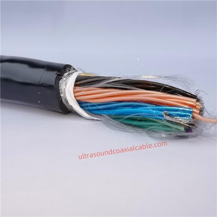
High-Performance Ultrasound Coaxial Cable Assembly: 42AWG to 30AWG, 6.6mm OD, 18GHz Bandwidth Engineered for precision in medical imaging and industrial applications, this customizable coaxial cable assembly delivers exceptional signal.
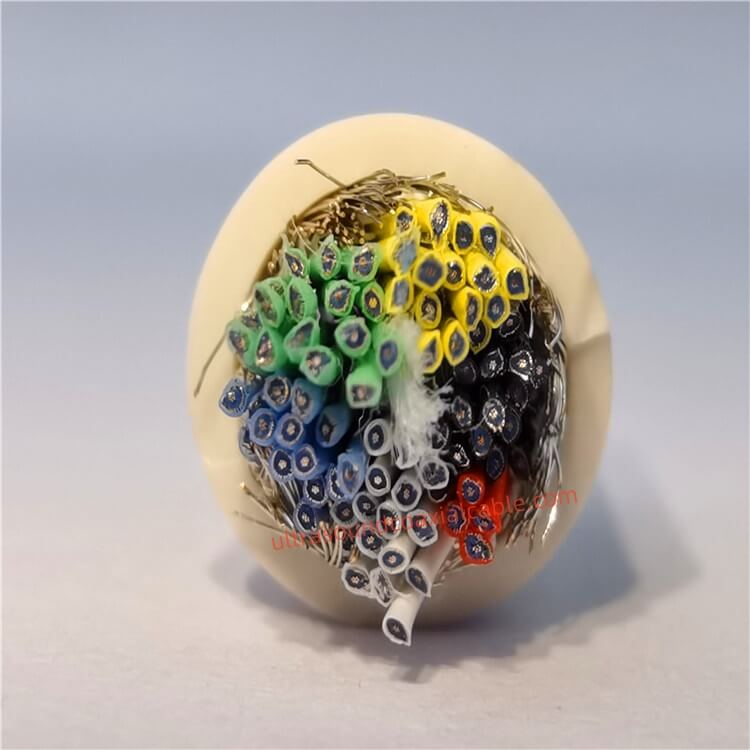
Product OverviewThe Ultrasound Coaxial Cable is a specialized cable engineered to deliver ultra-low signal loss, exceptional shielding, and unmatched durability in critical environments. Designed for medical imaging, industrial testi.
Feel free to reach out to us for any inquiries or orders.