Ultrasound coaxial cables are the critical lifelines of medical imaging systems, transmitting delicate signals between the probe and the main… - Professional Ultrasound Coaxial Cable Solutions
Learn more about, latest news, frequently asked questions
Ultrasound coaxial cables are the critical lifelines of medical imaging systems, transmitting delicate signals between the probe and the main unit. When these cables fail, they can compromise diagnostic accuracy and lead to costly downtime. This guide provides comprehensive methods for testing ultrasound coaxial cables, ensuring your medical equipment maintains peak performance.
Ultrasound coaxial cables in medical probes are typically multi-core high-shielding cables containing dozens to hundreds of individual wires, each as fine as human hair . These cables employ sophisticated designs with multiple layers of shielding to protect against electromagnetic interference, which is crucial for maintaining signal integrity in environments with other medical imaging equipment .
Common points of failure include:
The cable segment near the probe head is particularly vulnerable to damage due to frequent flexing during examinations. Some manufacturers address this by implementing gradual rigidity designs where the sheath thickness increases near the probe head connection .
Begin with a thorough visual examination of the entire cable length. Look for obvious signs of damage including cuts, abrasions, stains, or exposed wiring . Pay special attention to the areas near connectors and strain reliefs, as these stress points are prone to failure.
Next, perform a manual flexibility test. Hold the scanhead by the strain relief and gently flex the cable while monitoring the ultrasound image, particularly the near field. If you observe image dropouts or noise generation during flexing, this indicates one or more broken conductors within the cable assembly .
Connector inspection is equally critical. Examine the connector for any bent, broken, or missing pins, as damaged pins can not only cause cable failure but may also damage the ultrasound system’s connector board, creating a cascade of problems . For B2B equipment managers, establishing regular visual inspection protocols can prevent small issues from escalating into major repairs.
Use a multimeter to check for continuity in the cable conductors. Measure the resistance of each conductor and compare values across similar lines; significant variations may indicate potential issues. Advanced testing can include impedance measurements using specialized equipment like cable analyzers that can detect impedance anomalies greater than 15%, which may indicate internal damage .
For a more comprehensive assessment, utilize pulse reflection methods similar to those used in industrial cable testing. The principle involves sending a low-voltage pulse through the cable and analyzing reflected waves for abnormalities. When pulses encounter damage points where impedance changes abruptly, they generate reflections that can be measured to locate faults precisely .
While scanning a tissue-mimicking phantom, slowly move the transducer across the surface while watching for image artifacts that correlate with cable position. Dark areas that move with specific cable bends typically indicate broken elements within the cable assembly . This functional test is particularly valuable as it assesses the cable under realistic operating conditions.
Advanced cable analyzers can perform HDTDR measurements that provide graphical representations of cable integrity. These systems detect and report the position of the largest impedance anomaly (if any are present) on the cable, with test tools typically reporting an anomaly if 15% or more of the test signal is reflected . This approach is particularly effective for identifying intermittent issues that may not appear during static testing.
Emerging research demonstrates that nonlinear ultrasound techniques can effectively assess interface conditions in complex cable systems. This method analyzes harmonic responses when ultrasonic waves pass through materials, detecting subtle changes in mechanical properties that may indicate early-stage degradation . While primarily used for industrial power cables currently, this technology shows promise for medical cable applications where early detection of degradation is valuable.
The table below summarizes key cable testing approaches:
| Method | Best Use Case | Equipment Needed | Detection Capability |
|---|---|---|---|
| Visual Inspection | Routine preventive maintenance | None | External damage only |
| Flex Testing | Intermittent image issues | Ultrasound system with phantom | Broken conductors during movement |
| Pulse Reflection | Locating specific damage points | Cable fault tester or TDR | Distance to fault, severity assessment |
| HDTDR | Comprehensive quality certification | Advanced cable analyzer (e.g., Fluke DTX/DSX) | Graphical fault representation, impedance anomalies |
Implementing a structured maintenance protocol can significantly extend ultrasound cable lifespan. This includes proper storage techniques (hanging probes rather than coiling them), regular cleaning with appropriate disinfectants, and strain relief inspections . For healthcare facilities managing multiple systems, consider investing in specialized cable testing equipment that can document performance trends over time, enabling predictive maintenance before catastrophic failures occur.
Advanced coaxial designs like those incorporating micro coaxial technology offer enhanced durability through features such as medical-grade PU or silicone jackets and high-density shielding. When specifying replacement cables, look for designs that balance flexibility with durability, particularly in high-stress areas near the probe head .
While basic testing can identify cable issues, many repairs require specialized expertise. When internal conductors are damaged or shielding is compromised, seek professional repair services with ISO 13485:2016 certification, which specifies requirements for quality management systems in medical device applications . These specialized facilities have the equipment and expertise to perform comprehensive repairs that restore original performance characteristics.
By implementing a systematic approach to ultrasound coaxial cable testing, healthcare facilities can maintain optimal imaging performance, reduce equipment downtime, and extend the service life of valuable diagnostic equipment. Regular testing protocols not only identify existing issues but also help predict impending failures, allowing for planned maintenance that minimizes disruption to clinical operations .
Discover our most popular furniture pieces that are loved by customers worldwide.
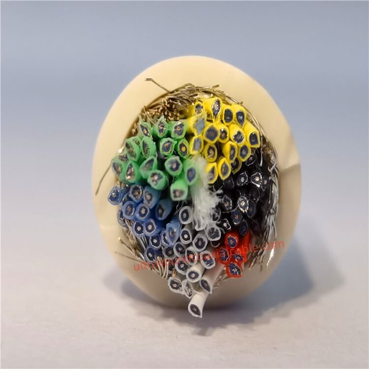
Product OverviewThe Ultrasound Coaxial Cable is a specialized cable engineered to deliver ultra-low signal loss, exceptional shielding, and unmatched durability in critical environments. Designed for medical imaging, industrial testi.
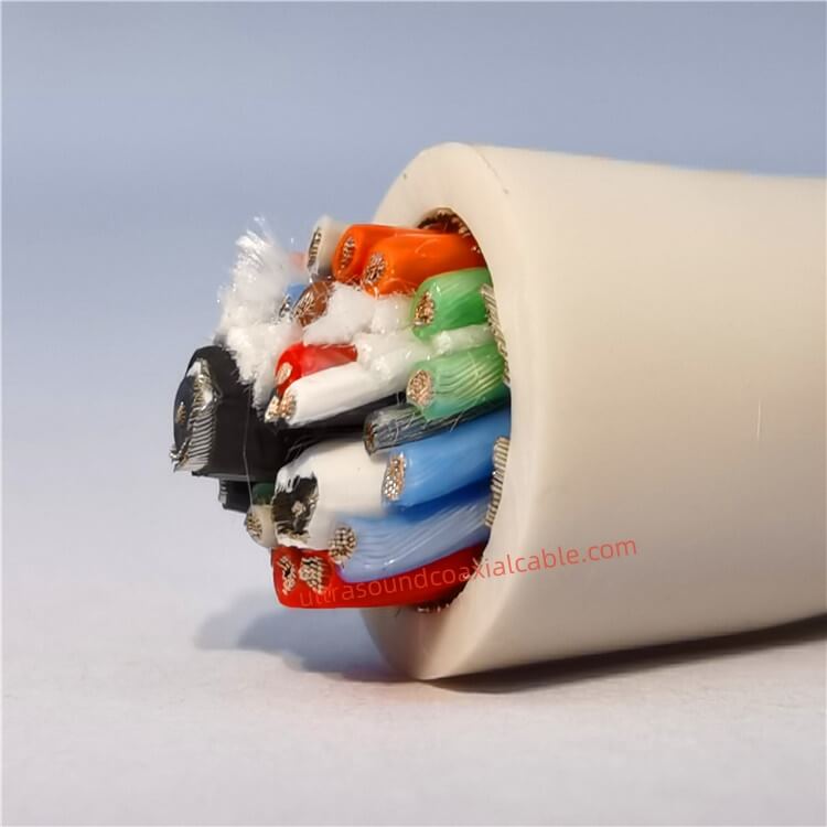
High-Precision 138-Core Medical Ultrasound Coaxial Cables | 0.2mm Ultra-Fine Biocompatible Design for Diagnostic Imaging Product Overview Engineered for advanced medical imaging systems, our 138-Core Medical Ultrasound Probe Coa.
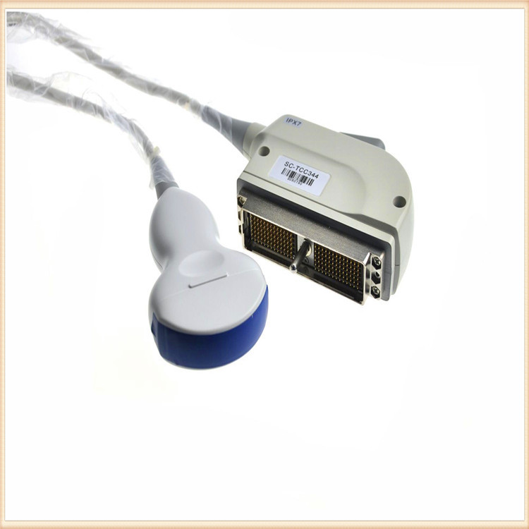
High-Performance Military Ultrasound Coaxial Cables: Built for Extreme Conditions Designed to meet the demanding requirements of military, aerospace, and medical applications, our Military-Grade Ultrasound Coaxial Cables deliver except.

High-Performance Flexible Coaxial Cable for Medical Imaging & Ultrasound Systems Designed for demanding applications in medical imaging, industrial diagnostics, and high-frequency signal transmission, this ultra-flexible coaxial ca.
Feel free to reach out to us for any inquiries or orders.