How to Troubleshoot Common Issues with Ultrasound Coaxial Cable Connections | High-Quality Ultrasound Coaxial Cable | ultrasound coaxial cable Manufacturer & Factory-FRS

How to Troubleshoot Common Issues with Ultrasound Coaxial Cable Connections

Ultrasound coaxial cables are the critical lifeline between transducers and imaging systems, transmitting high-frequency signals essential for diagnostic accuracy. When… - Professional Ultrasound Coaxial Cable Solutions

Information

Learn more about, latest news, frequently asked questions

Ultrasound coaxial cables are the critical lifeline between transducers and imaging systems, transmitting high-frequency signals essential for diagnostic accuracy. When these cables fail, they can cause image distortion, signal loss, or complete system failure—potentially impacting patient care and operational efficiency. This comprehensive guide provides systematic troubleshooting methods for common ultrasound coaxial cable connection issues, helping technicians and healthcare professionals maintain peak system performance.

Understanding Ultrasound Coaxial Cable Anatomy

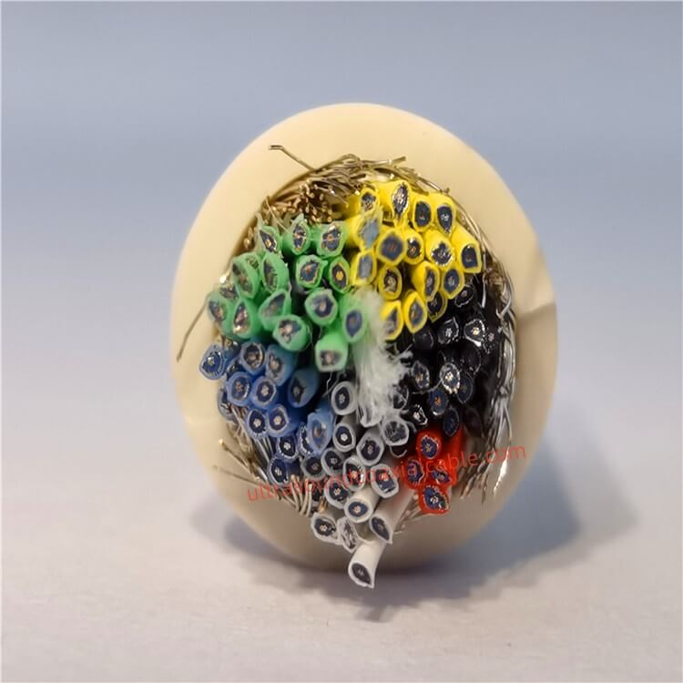
Before troubleshooting, it’s essential to understand what makes these cables unique. A typical ultrasound coaxial cable consists of multiple micro-coaxial wires—often 130-200 individual strands—each containing a central conductor, insulation layer, shielding, and outer jacket. These micro-coaxial wires can be as thin as 44-42 AWG, making them highly sensitive to physical stress and environmental factors. The entire assembly is engineered to transmit signals in the 1MHz–100MHz range with minimal loss, maintaining precise 50Ω impedance matching critical for real-time imaging accuracy.

Common Connection Issues and Diagnostic Steps

1. Signal Degradation and Image Distortion

Symptoms: Blurry images, increased noise or static, weak signal transmission, or intermittent connectivity.

Diagnostic Process:

  • Visual Inspection: Check for visible damage to the outer jacket, including cuts, kinks, or crushed sections, particularly near connectors and stress relief points where fatigue failures typically initiate.
  • Continuity Test: Use a multimeter to test continuity between the center pin and outer shield. A healthy cable should show near-zero resistance (<1 ohm). Spikes or infinite resistance indicate broken conductors.
  • Signal Path Analysis: Measure signal characteristics at multiple points in the system to isolate the degradation source. Compare signals with reference cables to determine if the issue is cable-related or system-based.

Root Causes: Damaged shielding allowing electromagnetic interference (EMI), broken inner conductors from repeated bending, or impedance mismatches at connection points.

2. Physical Damage and Connector Issues

Symptoms: Loose connections, bent or broken connector pins, corrosion on contact points, or intermittent signal loss.

Diagnostic Process:

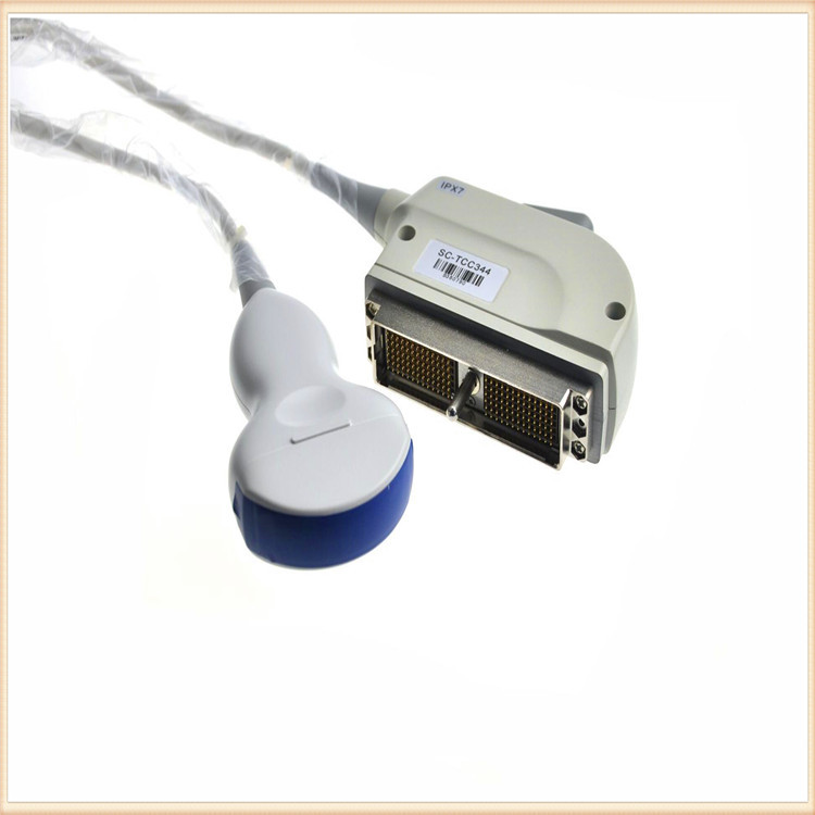
  • Connector Inspection: Check for loose fittings, bent pins, or corrosion on BNC, SMA, or LEMO connectors. Ensure connectors are fully seated and locking mechanisms are engaged.
  • Contact Resistance Measurement: Use a multimeter to measure resistance at connector points. Increased resistance indicates developing corrosion or wear.
  • Bend Radius Assessment: Examine the cable for sharp bends or kinks that exceed the minimum bend radius (typically 10 times the cable diameter). These can deform internal conductors and shielding.

Root Causes: Improper handling during plugging/unplugging, excessive bending near connectors, or exposure to moisture and contaminants.

3. Environmental Stress Factors

Symptoms: Brittle outer jacket, discoloration, mold growth near seals, or signal degradation in extreme temperatures.

Diagnostic Process:

  • Environmental History: Document the cable’s exposure to UV light, moisture, extreme temperatures (-40°C to +125°C), or chemical sterilization processes.
  • Material Degradation Check: Look for yellowing, brittleness, or cracking in the outer jacket, which may indicate oxidation or UV damage.
  • Temperature Cycling Test: Monitor signal performance during temperature variations to identify thermal stress-related failures.

Root Causes: UV exposure degrading outer jackets, moisture ingress corroding shielding and conductors, or thermal cycling causing material fatigue.

Step-by-Step Troubleshooting Protocol

Phase 1: Visual and Physical Inspection

  1. Systematic Visual Check: Inspect the entire cable length, paying special attention to areas near connectors, stress relief points, and high-traffic zones where cables are frequently moved or bent.
  2. Connector Integrity: Verify that connectors are clean, free of corrosion, and properly seated. Use isopropyl alcohol and a lint-free cloth to clean contact points.
  3. Bend Radius Verification: Ensure all cable bends maintain at least 10 times the cable diameter to prevent internal wire breakage and shield deformation.
  4. Shielding Assessment: Check for exposed shielding or foil layers, which can lead to EMI interference and signal noise.

Phase 2: Electrical Testing

  1. Continuity Test: Use a multimeter to test each conductor from end to end. Infinite resistance indicates a broken conductor.
  2. Impedance Measurement: Verify that the cable maintains 50Ω impedance (±2%) across its length. Impedance mismatches can cause signal reflections and image artifacts.
  3. Signal Attenuation Measurement: Compare signal strength at both ends of the cable. Excessive attenuation may indicate damaged conductors or poor shielding.
  4. Short Circuit Check: Test for shorts between the center conductor and shield, which can cause system malfunctions or safety hazards.

Phase 3: Environmental Testing

  1. Temperature Performance: Test the cable across its specified temperature range (-40°C to +125°C for industrial-grade cables) to identify thermal degradation.
  2. Flex Cycle Testing: For cables in portable applications, perform flex cycle tests to verify they can withstand the required number of bending cycles without signal degradation.
  3. Sterilization Compatibility: For medical applications, verify that the cable can withstand repeated sterilization cycles (autoclaving up to 134°C or chemical sterilization) without material degradation.

Advanced Diagnostic Tools and Techniques

Time-Domain Reflectometry (TDR)

TDR sends a pulse down the cable and measures the time it takes for reflections to return, pinpointing the exact location of faults such as breaks, shorts, or impedance mismatches. This non-destructive testing method can identify hidden faults that visual inspection might miss.

Thermal Imaging

Infrared cameras can detect hot spots along the cable length, indicating areas of high resistance or poor connections that may lead to failure. This technique is particularly useful for identifying developing issues before they cause complete failure.

Signal-to-Noise Ratio (SNR) Analysis

Measure the SNR at both ends of the cable to quantify signal degradation. A significant drop in SNR indicates cable-related issues rather than system problems. Advanced systems can use this data to implement signal compensation algorithms that reconstruct original signals from degraded received signals.

Preventive Maintenance Strategies

Regular Inspection Regimen

Implement monthly visual inspections of all ultrasound coaxial cables, documenting any signs of wear, damage, or performance degradation. Create a maintenance log to track repairs and identify recurring issues.

Proper Cable Management

  • Bend Radius Management: Maintain bend radii of at least five times the cable diameter to prevent shield deformation and center conductor displacement.
  • Strain Relief: Use reinforced strain relief boots at connection points to distribute stress and prevent fatigue failures.
  • Routing Optimization: Route cables away from high-interference sources (power lines, motors) and avoid sharp bends or pinch points.

Environmental Protection

  • UV-Resistant Jackets: For cables exposed to sunlight, use UV-resistant materials to prevent brittleness and cracking.
  • Weatherproof Enclosures: Protect outdoor installations with weatherproof enclosures to prevent moisture ingress.
  • Temperature Management: Avoid exposing cables to extreme temperature fluctuations that can cause material fatigue.

When to Replace vs. Repair

Repairable Issues

  • Minor cuts or abrasions on the outer jacket
  • Loose or corroded connectors (replace connectors only)
  • Minor shielding damage that can be properly re-shielded
  • Single conductor breaks that can be spliced with proper tools

Replacement Required

  • Multiple conductor breaks or extensive shielding loss
  • Severe physical damage (crushed or kinked sections)
  • Age-related deterioration (cables older than 5-10 years showing increased attenuation)
  • Complex damage requiring specialized equipment for proper repair

Industry Standards and Quality Assurance

Key Certifications

When selecting replacement cables or repair services, ensure compliance with industry standards:

  • ISO 13485: Medical device quality management systems
  • FDA Approval: For medical-grade cables used in diagnostic imaging
  • RoHS and REACH: Environmental compliance for hazardous substances
  • UL Certification: Safety standards for electrical components

Performance Specifications

High-quality ultrasound coaxial cables should meet these critical specifications:

  • Attenuation: <0.5 dB/m at 50MHz
  • Shielding Effectiveness: >90% EMI rejection
  • Impedance: 50Ω ±2%
  • Temperature Range: -40°C to +125°C (industrial grade)
  • Flex Life: 3,000+ flex cycles for medical applications

Market Considerations and Future Trends

The global coaxial cable market is projected to grow at a 4.6% CAGR from 2025 to 2030, driven by increasing demand in medical imaging, telecommunications, and industrial applications. Key trends include:

  • Miniaturization: Ultra-thin cables (0.2mm diameter) for catheters and endoscopic devices
  • Enhanced Shielding: Multi-layer shielding configurations providing >100 dB EMI rejection
  • Smart Cables: Embedded sensors for real-time health monitoring and predictive maintenance
  • Sustainability: Recyclable materials and eco-friendly manufacturing processes

Professional Support and Manufacturer Partnerships

For complex issues or mission-critical applications, partnering with a specialized manufacturer like FRS can provide access to:

  • Technical Expertise: 20+ years of experience in micro-coaxial manufacturing
  • Custom Solutions: Tailored cable designs for specific applications and environments
  • Certified Repairs: Professional repair services with warranties
  • Preventive Maintenance Programs: Scheduled inspections and performance monitoring

Conclusion

Effective troubleshooting of ultrasound coaxial cable connections requires a systematic approach combining visual inspection, electrical testing, and environmental assessment. By understanding the cable’s anatomy, recognizing early warning signs, and implementing preventive maintenance strategies, healthcare facilities and industrial users can minimize downtime, extend cable lifespan, and maintain diagnostic accuracy. For critical applications, investing in high-quality cables from reputable manufacturers and establishing professional maintenance partnerships ensures long-term reliability and optimal system performance.

Hot Selling Products

Discover our most popular furniture pieces that are loved by customers worldwide.

Ultra-Flexible Coaxial Cable for Ultrasound Transducers – 44AWG, 0.15dB/m Attenuation at 1GHz

Ultra-Flexible Coaxial Cable for Ultrasound Transducers – 44AWG, 0.15dB/m Attenuation at 1GHz

High-Performance Flexible Coaxial Cable for Medical Imaging & Ultrasound Systems Designed for demanding applications in medical imaging, industrial diagnostics, and high-frequency signal transmission, this ultra-flexible coaxial ca.

High-Precision Ultrasound Coaxial Cable for Medical Imaging – Low Noise, Flexible Design, 42AWG

High-Precision Ultrasound Coaxial Cable for Medical Imaging – Low Noise, Flexible Design, 42AWG

Ultra-Flexible 42AWG Medical-Grade Coaxial Cables for High-Precision Ultrasound Imaging Designed for demanding medical imaging applications, our Ultra-Flexible 42AWG Coaxial Cables deliver exceptional signal integrity, noise reduction,.
Ultrasound Coaxial Cable|High-Performance Signal Transmission for Precision Applications

Ultrasound Coaxial Cable|High-Performance Signal Transmission for Precision Applications

‌‌Product Overview‌The ‌Ultrasound Coaxial Cable‌ is a specialized cable engineered to deliver ultra-low signal loss, exceptional shielding, and unmatched durability in critical environments. Designed for medical imaging, industrial testi.
Military-Grade Ultrasound Coaxial Cable – High-Temperature Resistance, 100daN Compression Strength

Military-Grade Ultrasound Coaxial Cable – High-Temperature Resistance, 100daN Compression Strength

High-Performance Military Ultrasound Coaxial Cables: Built for Extreme Conditions Designed to meet the demanding requirements of military, aerospace, and medical applications, our Military-Grade Ultrasound Coaxial Cables deliver except.

Contact Us

Feel free to reach out to us for any inquiries or orders.

Call Us

Have a question? Give us a call!

                   +8618818785005(Whatsapp)

Email Us

Send us an email and we'll get back to you soon.

sales@custom-cable-assemblies.com
       
Home Products Contact