Maximizing Signal Integrity in Long-Distance Ultrasound Coaxial Cable Installations: A Practical Guide In medical imaging, industrial testing, and research applications… - Professional Ultrasound Coaxial Cable Solutions
Learn more about, latest news, frequently asked questions
Maximizing Signal Integrity in Long-Distance Ultrasound Coaxial Cable Installations: A Practical Guide
In medical imaging, industrial testing, and research applications where ultrasound technology is critical, the reliability of data transmission can make or break system performance. At the heart of this lies a often-overlooked component: the ultrasound coaxial cable. For long-run installations—whether spanning several meters in a large hospital imaging suite or hundreds of feet in an industrial facility—signal loss, interference, and degradation remain persistent challenges. This guide dives into the key factors that affect ultrasound coaxial cable performance over extended distances and outlines actionable strategies to optimize their functionality, ensuring clear, consistent signals from transducer to display.
Ultrasound systems rely on coaxial cables to transmit high-frequency electrical signals between transducers and processing units. Unlike shorter runs, long cables introduce unique obstacles:
To mitigate these challenges, engineers and installers must prioritize design and material selection that addresses the unique demands of extended cable runs. Below are proven strategies to enhance performance:


The core of any coaxial cable—the central conductor—plays a pivotal role in minimizing signal loss. For long runs, opt for high-purity copper (e.g., OFHC: Oxygen-Free High-Conductivity copper) instead of cheaper alternatives like aluminum or copper-clad steel. Copper’s superior conductivity reduces resistive losses, ensuring more of the original signal reaches its destination. Additionally, stranded copper cores (as opposed to solid cores) offer greater flexibility, reducing the risk of breakage in applications where cables are frequently moved or bent.
Shielding is critical for blocking EMI and preventing signal leakage. Long-run ultrasound coaxial cables should feature multi-layer shielding to maximize protection. Common configurations include:
For applications requiring the highest performance, some manufacturers use tri-shield designs or add a conductive polymer layer between shields to further reduce leakage.
Impedance consistency is non-negotiable for long-distance ultrasound cables. A cable with a 50-ohm impedance (standard for most ultrasound systems) ensures that the signal travels without reflection. To maintain this, manufacturers must tightly control the dimensions of the dielectric insulator (the material between the inner and outer conductors) and the spacing between the shield and center conductor. Even minor deviations can cause reflections; for example, a 1% increase in dielectric diameter can lead to a 2% drop in impedance, resulting in measurable signal loss over 10 meters.
The dielectric insulator (commonly polyethylene or PTFE) separates the inner and outer conductors and determines the cable’s velocity factor and attenuation. For long runs, choose dielectrics with low dielectric constant (Dk) and low loss tangent. PTFE, for instance, has a Dk of ~2.1 and a very low loss tangent, making it ideal for high-frequency, long-distance applications. This material minimizes signal delay and energy loss, preserving the integrity of the ultrasound pulse.
While thicker cables generally offer lower attenuation, they may be impractical for installations with tight spaces or frequent movement. Balance is key:
Even the best cable will underperform if installed incorrectly. Follow these guidelines:
Over time, environmental factors like moisture or temperature cycles can degrade a cable’s performance. Implement a maintenance schedule that includes:
When it comes to reliable, high-performance ultrasound coaxial cables for long-distance installations, FRS stands out as a trusted partner. With over two decades of expertise in designing and manufacturing specialized coaxial solutions, FRS combines cutting-edge materials science with rigorous testing to deliver cables that exceed industry standards.
Why Choose FRS?
For medical professionals, engineers, and system integrators seeking to optimize their ultrasound setups, FRS coaxial cables are the clear choice. Experience the difference that precision engineering makes—choose FRS for signal integrity that lasts.
In long-distance ultrasound installations, the right coaxial cable is more than just a conductor—it’s the backbone of clear, accurate imaging. By prioritizing material quality, shielding, impedance matching, and proper installation, you can transform signal loss from a challenge into a non-issue. And with FRS’s expertise, you gain a partner dedicated to delivering cables that perform, day in and day out.
Discover our most popular furniture pieces that are loved by customers worldwide.
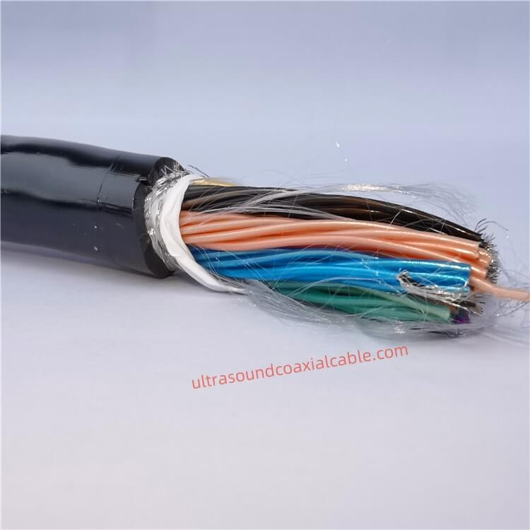
High-Performance Ultrasound Coaxial Cable Assembly: 42AWG to 30AWG, 6.6mm OD, 18GHz Bandwidth Engineered for precision in medical imaging and industrial applications, this customizable coaxial cable assembly delivers exceptional signal.

High-Performance Flexible Coaxial Cable for Medical Imaging & Ultrasound Systems Designed for demanding applications in medical imaging, industrial diagnostics, and high-frequency signal transmission, this ultra-flexible coaxial ca.
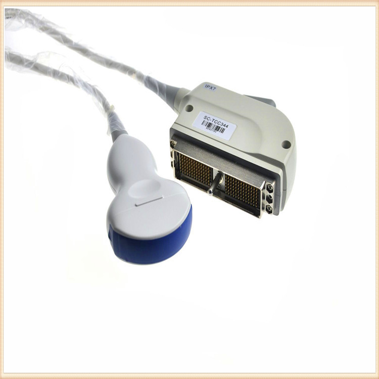
High-Performance Military Ultrasound Coaxial Cables: Built for Extreme Conditions Designed to meet the demanding requirements of military, aerospace, and medical applications, our Military-Grade Ultrasound Coaxial Cables deliver except.
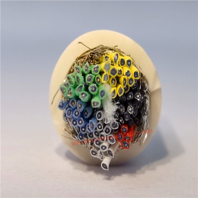
Product OverviewThe Ultrasound Coaxial Cable is a specialized cable engineered to deliver ultra-low signal loss, exceptional shielding, and unmatched durability in critical environments. Designed for medical imaging, industrial testi.
Feel free to reach out to us for any inquiries or orders.